Bullet Expansion (Mechanical Coil Expansion): A Step-by-Step Guide to Fin-Tube Assembly
Jump to section
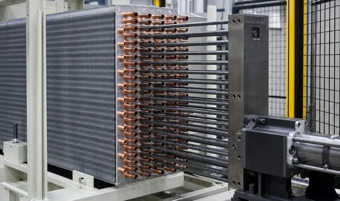
In a round-tube, plate-fin coil, the tubes must pass through many small fin collars during assembly. A small amount of clearance makes this possible. However, that same clearance can leave gaps between the tube and the fins. Those gaps weaken the heat path through the coil.
Bullet expansion removes this clearance. A solid tool passes through each tube and enlarges it by a controlled amount. The tube wall then presses against the fin collars. This creates close metal-to-metal contact and helps lock the coil core together.
The method sounds simple, but the result depends on the whole setup. Tube size, wall thickness, fin geometry, tool condition, support, speed, and friction all matter. This guide explains how mechanical coil expansion works, how it fits into fin-tube assembly, and how manufacturers can control common defects.
What Is Bullet Expansion in Fin-Tube Assembly?
Bullet expansion is a mechanical method used to enlarge tubes after they have been inserted through a plate-fin stack. It is one common form of mechanical coil expansion. The process is mainly used for round-tube, plate-fin coils found in HVAC and refrigeration equipment.
The term does not cover every type of finned tube. Extruded fin tubes, spiral-wound fin tubes, and welded fin tubes use different ways to join the fin and the base tube. Rolling a tube into a thick tubesheet is also a different process.
How an Expansion Bullet Creates a Tube-to-Fin Interference Fit
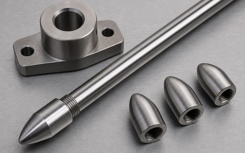
An expansion bullet creates the fit by making the tube slightly larger than its starting size. The bullet is a smooth, hard tool fixed to an expander rod. Its working diameter is larger than the starting inner diameter of the tube.
As the machine drives the bullet through the tube, the tube wall moves outward. Part of this change remains after the tool has passed. The outer tube wall then presses against the fin collar. The result is an interference fit between the tube and the fin.
Three parts should not be confused:
- The bullet, or mandrel, is the shaped tool that expands the tube.
- The expander rod carries and guides the bullet through the tube.
- The fin collar is the raised edge around the hole in each plate fin.
All three affect the final contact. A correct bullet cannot make up for a damaged collar or a bent rod.
Where Mechanical Coil Expansion Fits in HVAC Coil Production
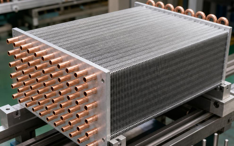
Mechanical coil expansion takes place after the fins and hairpin tubes have been prepared and laced together. A common production order is fin stamping, fin stacking, hairpin tube insertion, tube expansion, tube-end forming, return-bend or header assembly, brazing, and final testing.
The fin holes and collars are made during the upstream stamping stage. For certain refrigerator evaporator projects, an aluminum fin plate stamping line can form fins to an approved product drawing before assembly begins.
The exact order can change with the coil design. For example, some plants form a bell or flare during the expansion cycle, while others use a separate station. The approved process sheet should define the order for each coil model.
Why Does Bullet Expansion Matter to Fin-Tube Coil Performance?
Bullet expansion matters because the fins can transfer heat well only when they have stable contact with the tubes. It also helps the loose tube-and-fin stack become a more stable coil core. Yet more expansion is not always better. The goal is a repeatable fit, not the highest possible force.
How Tight Tube-to-Fin Contact Supports Heat Transfer
Heat in an air coil follows a clear path. It moves from the fluid to the tube wall, from the tube wall to the fins, and from the fins to the air. A gap between the tube and a fin adds thermal contact resistance to this path.
Controlled expansion reduces that gap and creates closer contact around the fin collar. This allows the fin area to take part in heat transfer as intended. Uneven expansion can produce uneven contact, even when the outside of the coil looks acceptable.
Over-expansion does not guarantee better heat transfer. It can deform the collar, thin the tube wall, or damage an inner tube surface. A qualified process must balance contact, tube condition, coil dimensions, and production repeatability.
How Mechanical Expansion Strengthens the Coil Core
Mechanical expansion also helps hold the fin pack in place. Before expansion, the fins and tubes can still move in relation to each other. After expansion, the contact between the collars and tubes makes the core more stable during handling and later assembly.
This joint does not replace the coil frame, end plates, brazed connections, or other structural parts. Its main roles are to support tube-to-fin contact and to help keep the core aligned.
How Does Bullet Expansion Work Step by Step?
Bullet expansion usually follows six controlled stages. Each stage protects the next one. A clean tube cannot prevent a defect if the rod pattern is wrong, and correct tooling cannot prevent damage if the coil has poor support.
Step 1: Prepare the Fin Stack and Hairpin Tubes
Preparation starts with the current product drawing and process specification. The operator should confirm the tube material, outer diameter, wall thickness, temper, inner surface, hairpin length, fin material, fin pitch, collar height, and fin-hole size.
Nominal tube size alone is not enough. Two tubes with the same stated outer diameter can have different inner diameters because their wall thicknesses differ. Internally grooved tubes also need tooling and inspection methods suited to their inner shape.
The tube bore should be free from chips, hard particles, heavy oxide, and other dirt that could score the tube or bullet. Tube ends should not have burrs, dents, or sharp edges. The fin stack should have aligned holes and sound collars. Cracked, folded, or uneven collars can cause poor contact later.
Before a new material lot or coil design enters full production, the plant should run a sample and confirm the process window. This is safer than selecting a bullet from nominal dimensions alone.
Step 2: Lace and Align the Hairpin Tubes Through the Fin Collars
Hairpin tubes should pass through the fin collars without heavy force. The fin stack needs support so the holes stay in line while each tube is inserted. Guides can help keep the tube straight and protect the fin edges.
High insertion force is a warning sign. It may point to poor hole alignment, bent tubes, burrs, the wrong collar size, or a damaged fin pack. Forcing the tube through can fold collars, scratch the tube, or push the fins out of position.
After lacing, the operator should check hairpin bend location, open-end projection, row alignment, and fin-pack condition. Correcting an error is easier before the core enters the expander.
Step 3: Match the Bullet, Rod Pattern, and Expansion Setup
The bullet must match the actual tube bore and the approved final fit. Its lead-in shape, working diameter, surface finish, and length can affect load and tube condition. The rod pattern must also match the tube layout so each required tube leg is expanded in the right position.
The setup should define stroke length, start position, stop position, rod arrangement, and any bell or flare tooling. It should also state whether all tubes are expanded in one cycle or in approved groups.
A small change in tube wall or inner diameter can change the result. For this reason, a plant should identify bullet sets by controlled tool numbers and should not mix worn and new bullets in one pattern without approval.
Step 4: Support the Coil and Align the Expansion Tooling
The coil needs firm, even support before the machine begins its stroke. The fixture should hold the end plates or approved support areas without crushing the fin pack. The rods should line up with the tube bores and move on the same axis as the tubes.
Poor alignment raises side load. It can bend a rod, scratch one side of a tube, distort a collar, or buckle a thin tube. The stroke should also stop before the bullet reaches an unapproved area, such as a tight hairpin bend.
Coil length, row count, tube size, and fixture design all change the load path. A support method that works for a short, two-row coil may not suit a long or deep coil.
Step 5: Run the Controlled Mechanical Expansion Pass
During the expansion pass, the machine drives the bullets through the tubes at the approved rate and stroke. The tubes expand outward and press against the fin collars. Modern equipment may also record position, cycle time, force, or motor load, depending on the machine design.
The operator should watch for a sudden load rise, unusual sound, uneven rod movement, or a stop before full stroke. These signs can point to dirt, a blocked tube, poor alignment, a damaged bullet, or the wrong setup. The correct response is to stop and inspect the cause. An extra pass should not be used as an unplanned repair.
Machine guards, safe loading rules, and the equipment maker’s service instructions remain part of the process. Tool checks should be done with the machine in a safe state.
Step 6: Inspect the Coil and Complete Required Tube-End Forming
The first inspection begins as soon as the rods retract. The operator should check tube-end position, hairpin position, fin-pack length, end-plate condition, fin flatness, and any visible scratches or splits.
If the process includes tube-end sizing, belling, or flaring, those features should be checked against the drawing. If end forming takes place later, the expanded tube ends must still have the correct length and shape for the next station.
The coil can then move to return-bend or header assembly, brazing, and the required leak and pressure tests. Expansion inspection and leak testing are related quality steps, but they do not check the same feature.
Which Settings Control Bullet Expansion Quality?
Bullet expansion quality is controlled by the fit between the product, tool, machine, and fixture. No single expansion rate works for every coil. The correct values must come from trials, measurements, and an approved process for the exact tube and fin combination.
Match the Bullet to the Tube and Fin Geometry
Tool selection should use actual dimensions. Key inputs include tube inner and outer diameter, wall thickness, material, temper, internal grooves, fin-hole diameter, collar height, fin material, fin hardness, fin pitch, and coil depth.
Plants may describe the amount of expansion in different ways. One useful production check is the change in measured tube outer diameter:
Measured OD change (%) = (OD after expansion − OD before expansion) ÷ OD before expansion × 100
For example, if a trial tube changes from 9.52 mm to 9.70 mm, the measured OD change is about 1.9%. This is only a math example, not a target for every 9.52 mm tube. The correct result still depends on wall thickness, tube temper, collar geometry, and the plant’s approved design.
Because factories may use different formulas for an “expansion ratio,” every inspection record should state the formula and measurement points. A number without a defined method is hard to compare.
Control Speed, Friction, Tool Condition, and Approved Lubrication
Friction affects both surface quality and expansion load. A dirty, rough, or worn bullet can raise drag and leave long marks inside the tube. A bent rod can add side load even when the bullet diameter is correct.
Bullet diameter and surface finish should be checked at set intervals. Rods, threads, guides, and mounting points also need inspection. A visual check alone may miss slow tool wear, so the plant should use defined measurement limits.
Any lubricant must be approved for the tube material and the full production process. Residue can affect cleaning, brazing, refrigerant-system cleanliness, or later coating. A general shop oil should not be added without process approval.
Manage Coil Support, Tube Shrinkage, and End Position
Mechanical bullet expansion can shorten the tube in the axial direction. Radial deformation, friction, tube condition, and the way the coil is held all affect this change. The amount is not constant across all coil designs.
Manufacturers normally control this issue through sample trials, hairpin length allowance, machine setup, and final tube-end checks. A simple shrinkage record can use this formula:
Tube shrinkage (%) = (length before expansion − length after expansion) ÷ length before expansion × 100
The measurement points must stay the same from one trial to the next. End position matters because return bends, headers, and brazed joints need the tube to reach the correct depth.
What Common Bullet Expansion Defects Occur—and Why?
The most common defects are under-expansion, over-expansion, uneven expansion, tube shrinkage, scratches, and buckling. A visible symptom does not always prove one cause. The plant should compare the defect with tool measurements, setup records, material data, and machine load.
Under-Expansion and Poor Tube-to-Fin Contact
Under-expansion leaves weak or uneven contact between the tube and fin collars. Possible causes include a bullet that is too small, tool wear, a larger-than-expected tube bore, incomplete stroke, or mismatched fin-hole geometry.
The coil may not show a large outside defect. That is why the process needs dimensional checks and a qualified contact test instead of visual inspection alone.
Over-Expansion, Tube Thinning, and Fin Collar Damage
Over-expansion places too much strain on the tube and collar. It may thin the tube wall, split a weak area, crush or crack a collar, distort the fins, or damage an internally grooved surface.
Likely causes include an oversized bullet, the wrong tube data, an extra unapproved pass, poor tool alignment, or a material change that was not added to the setup. The correction should address the cause rather than only lowering machine speed.
Tube Shrinkage, Buckling, Scratching, and Uneven Expansion
These defects often point to friction, alignment, support, or mixed process conditions. For example, a long scratch may come from a damaged bullet or debris, while different tube-end heights may come from uneven shrinkage or mixed hairpin lengths.
The table below gives a practical starting point for troubleshooting. It does not replace the plant’s own control plan.
| Observed defect | Likely causes | Recommended check |
| Loose fins or poor collar contact | Small or worn bullet; large tube bore; incomplete stroke; wrong fin hole | Measure the bullet and tube; confirm stroke; inspect sample contact |
| Split tube or damaged collar | Oversized bullet; wrong wall or temper; repeated pass; misalignment | Verify material lot and tool number; inspect tube wall and collars |
| Long inner-wall scratches | Dirty or rough bullet; chips in tube; bent rod; poor lubrication control | Clean the bore; inspect bullet finish and rod straightness |
| Uneven tube-end height | Variable shrinkage; mixed hairpin lengths; uneven support; wrong stop position | Compare before-and-after lengths; check fixture and machine stop |
| Buckled tube or bent rod | High side load; poor alignment; weak support; blocked tube | Check rod-to-tube alignment, guides, support, and tube bore |
| Different results across one coil | Mixed tool wear; uneven collars; tube variation; rod-pattern error | Map defects by tube position; compare tools, fins, and material data |
How Is Bullet Expansion Quality Checked?
Quality is checked through product measurements, tool control, process records, and final coil tests. No single check can confirm every part of the result. The control plan should cover the joint, the coil dimensions, and the later sealed circuit.
Check Coil Dimensions, Tube-End Position, and Fin Condition
The first checks are direct and practical. They include overall coil size, fin-pack length, end-plate position, tube-end projection, hairpin bend position, fin spacing, and visible tube or collar damage.
Measurements should use fixed points and approved gauges. If tube-end projection is important for a return bend or header, the drawing should state both the target and tolerance. A general note such as “ends even” is not enough for repeatable production.
Verify Expansion Consistency and Tube-to-Fin Contact
Expansion consistency can be checked with tube dimensions, machine data, sample sections, or a defined mechanical contact test. The best method depends on the product and factory.
For a new setup, a plant may cut a trial sample to inspect the tube and collar around the joint. A pull or push test may also be used where the product specification defines the sample shape, direction, and acceptance limit. Such a test shows mechanical holding force. It does not measure thermal contact by itself.
During regular production, tool records and position-based inspection can reveal drift. If defects appear in the same tube locations, the rod pattern, guide plate, and local fin geometry deserve close review.
Separate Expansion Inspection from Post-Braze Leak Testing
Bullet expansion does not make the refrigerant circuit leak-tight. It joins the tube to the fins for thermal contact and core stability. The fluid path is sealed later at return bends, headers, distributors, or other connections.
Leak and pressure tests should take place after those joints are complete. Test pressure, holding time, test medium, and acceptance limits must follow the product design and applicable plant rules. A passed leak test does not prove that tube-to-fin contact is correct, and a passed expansion check does not replace leak testing.
Frequently Asked Questions About Bullet Expansion
The questions below address the main points that often cause confusion during coil design, production setup, and equipment selection.
Is Bullet Expansion the Same as Hydraulic Tube Expansion?
No. Bullet expansion uses a solid tool to enlarge the tube from the inside. Hydraulic or pressure expansion uses fluid or gas pressure to expand the tube wall without driving a solid bullet through the full tube length.
The two methods have different effects on tooling, inner tube features, cycle design, and axial shrinkage. Neither method is best for every coil. For a clear product example of the second method, BOBO’s automatic fin alignment and expanding machine is described for guided assembly and hydro-expansion of certain finned evaporators. It should not be treated as a mechanical bullet expander.
Why Do Tubes Become Shorter During Mechanical Expansion?
Tubes can become shorter because the metal moves as the diameter grows, while friction and end restraint add axial force. Tube material, wall thickness, bullet shape, lubrication, expansion amount, and fixture design all affect the change.
The practical solution is to measure shrinkage on approved trial coils and build the result into the hairpin length and setup. A fixed allowance copied from another coil may give the wrong end position.
Can Bullet Expansion Damage Small or Internally Grooved Tubes?
Yes, a poor setup can damage them. Small-diameter, thin-wall, and internally grooved tubes leave less room for tooling error. A wrong bullet can thin the wall, mark the grooves, buckle the tube, or cause uneven expansion.
This does not mean mechanical expansion cannot be used. It means the bullet profile, surface finish, support, speed, and inspection method must be developed for that exact tube. A sample trial is essential before volume production.
Does Bullet Expansion Make a Refrigerant Coil Leak-Tight?
No. Bullet expansion forms the tube-to-fin contact. It does not seal return bends, headers, or other refrigerant joints. Those joints still need the specified joining process and final leak and pressure tests.
Conclusion: Reliable Bullet Expansion Depends on Control, Not Maximum Force
Reliable bullet expansion comes from matching the tube, fin, tooling, support, and machine setup. Clean parts and correct alignment reduce damage. Controlled deformation creates stable tube-to-fin contact. Defined measurements then show whether the result remains within the approved process window.
The most important rule is simple: a larger bullet or a second pass is not an automatic fix. Every change can affect tube wall thickness, collar shape, shrinkage, and the next brazing step. Trials and clear records are safer than a universal expansion value.
Manufacturers planning a new fin-tube process can review BOBO Machine’s tube and fin processing equipment and custom machinery options. A technical review of the coil drawing, tube data, fin geometry, required output, and quality checks can help define a suitable production route.
Want to Know More About Our Products?
View All Products Now